1. Summary:
Am243x is the latest high-performance MCU + product launched by Ti sitaratm product line. It is a multi-core heterogeneous MCU with strong performance. It has four cortex r5f cores with 800MHz dominant frequency, one cortex m4f with 400MHz dominant frequency, and two Prus specifically for multi protocol industrial communication bus_ ICSSG(2 × Gigabit industrial communication subsystems) module can realize PROFINET IRT, PROFINET RT, Ethernet / IP, EtherCAT and other communication modes.
In the development of such multi-core heterogeneous MCU / CPU products, due to the complexity of the chip on the power rail and the richness of peripherals, it is inevitable to contact the complex boot link of the system and the challenges brought by multi-core debugging. Taking am243x LP evaluation board as an example, this paper makes a preliminary introduction to the booting related content of am243x, The whole startup process of rbl-sbl-app and the method of program burning are fully demonstrated.
2. The booting link of am243x after power on:
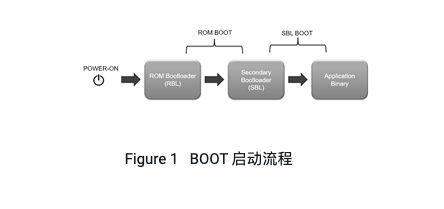
The following figure shows the complete boot process of am243x:
ROWER ON -> ROM Bootloader(RBL) -> Secondary Bootloader(SBL) -> Application Binary。 After power on, the chip initializes the internal logic, then executes the boot code in ROM, then executes the user-defined secondary boot code, and finally executes the application program
2.1 introduction to power on sequence and startup mode
Am243x chip has multiple power domains to supply power to different internal logic and peripherals. The following figure is the power on sequence diagram of am243x, which can be found in datasheet in more detail.

When the power supply sequence is met, MCU_ The porz signal finally releases the control of kernel reset, MCU_ The rising edge of porz latches sys_ Bootmode [0:15] the up and down states of these pins, so as to determine the startup mode and startup medium of the chip, and then the ROM bootloader reads the startup information.
Am243x has two main boot modes: host boot modes and memory boot modes.
Host boot modes: MCU starts from different peripherals, such as UART, Ethernet, USB and other interfaces;
Memory boot modes: MCU starts from different external storage media, such as QSPI flash, I2C EEPROM, SD card, USB flash disk and other memories;
Note: am243x has the functions of primary boot and backup boot, which means that am243x can be started with backup boot when the primary boot fails. This can be set by the bootmode pin.
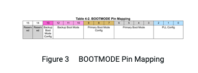
As for the bootmode pin configuration, we can see that it is composed of 16 signal lines, of which the upper two bits are reserved. Its 16bit corresponds to the 16 signal lines bootmode 00-15, and the corresponding pin in the schematic diagram is gpmc0_ AD0 – 15。
PLL config is configured for different external crystal oscillator frequencies.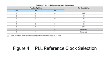
Figure 4 PLL Reference Clock Selection
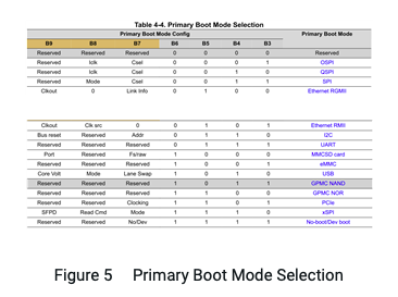
Primary Boot The mode is as follows:
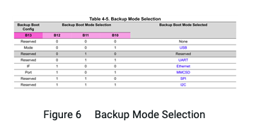
Figure 5 Primary Boot Mode Selection
The backup boot mode is as follows: (note that there are few startup modes in the backup mode)
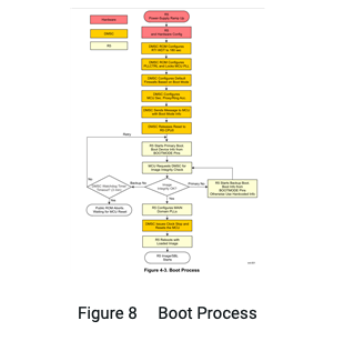
Figure 6 Backup Mode Selection
Note: since the pins used by ROM code for different startup interfaces or media are fixed, pay attention to selecting the corresponding pins during the design process. The detailed pin information can be viewed in the technical reference manual.
2.2 introduction to ROM startup process
The ROM code of am243x is divided into two parts: dmsc ROM code and public ROM code. Here, the full name of dmsc is device management security controller. Inside, there is a cortex m3 coprocessor with a main frequency of 250MHz, and the dmsc module is the main controller for chip startup
Dmsc ROM code: the code of dmsc ROM involves the following parts:
Equipment management;
In boot_ Configure boot vectors in CFG to control the reset release of R5 kernel. It should be noted that dmsc is the controller of R5 kernel during startup;
Configure IPC through master DMSs (data movement subsystem) and secure proxy;
Configure R5 kernel and PLL of sa2ul (security accelerator);
Analysis of x509 certification;
Sa2ul configuration of SHA512 algorithm for image integrity check;
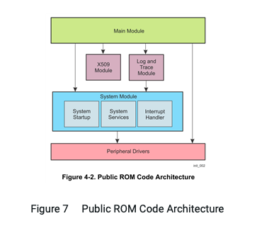
Public ROM code: the following figure shows the framework of public ROM code.
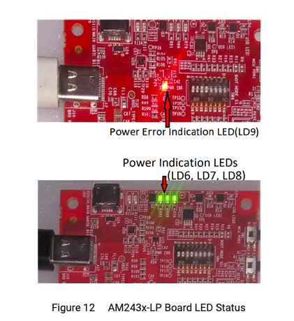
Figure 7 Public ROM Code Architecture
The main module is the top-level code cycle of the whole public ROM code. It can call the relevant function codes of x509 password authentication module, log trace module, system module and peripheral driver. It will be executed repeatedly here until the MCU receives the complete boot image, or it can be set in sleep mode by dmsc;
After the chip is powered on, the primary startup process can be divided into three parts:
Hardware part: it mainly refers to the power on process of the power supply and the initialization of the internal logic of the chip;
Dmsc part: dmsc ROM code will first configure the overflow time of watchdog WDT during startup to 180 seconds, then configure MCU PLL, configure corresponding firewall according to different boot modes, secure proxy / ring accelerator of MCU, and then dmsc will send boot mode info to MCU. Finally, dmsc releases the reset signal of R5 kernel, and R5 kernel starts to work;
R5 kernel: after the R5 kernel receives the boot device info sent by the dmsc (determined by the bootmode pin configuration), it starts to start through the corresponding boot mode. The R5 kernel will request the dmsc to check the image integrity of the received image code. If it succeeds, it will continue to execute downward. If the image of the primary boot is invalid, R5 will switch to backup mode for boot image reception and call dmsc again for image integrity check. In this way, the call will be repeated until the watchdog overflows for 180 seconds. At this time, MCU will be reset and all the above processes will be repeated.
After the image integrity check succeeds, the R5 kernel will configure the PLL of the main domain. Next, the dmsc will stop the clock and reset R5. R5 starts to execute the boot image after the reset (here, the boot image in RAM is not affected by R5 reset and is in the hold state). The whole boot process is completed and the chip starts the secondary boot process.
Figure 8 Boot Process
2.3 introduction to secondary SBL startup process
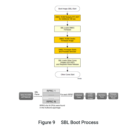
The full name of SBL is second boot loader, which is used to complete some initial configuration of the chip, copy sysfw of dmsc to on-chip RAM and load multi-core application code. The following figure is a typical SBL process The dmsc module will start the WDT watchdog again and set the watchdog overflow time to 180 seconds. R5 core 0 executes the SBL code. First copy the dmsc sysfw on flash to the on-chip RAM. After the dmsc ROM code checks the integrity of the sysfw image, load the sysfw into the dmsc module. Then the dmsc module will jump out of the dmsc ROM code and execute the dmsc sysfw code instead. SBL will continue to load and parse the application code of R5 core and set the startup address according to the image information. After completion, it will request dmsc to release the reset signal of other R5 cores, and all cores will start executing the program
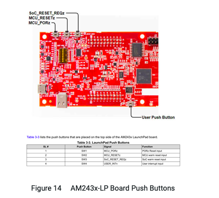
Figure 9 SBL Boot Process
3. Introduction to am243x LP:
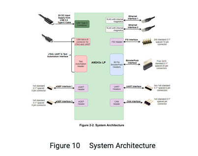
The am243x LP evaluation board provides rich functions and interfaces. The xds110 debugger is also integrated on the circuit board to facilitate users' burning and debugging. At the same time, the USB to UART function is also realized through the same USB interface for printing serial port log information.
Figure 10 System Architecture
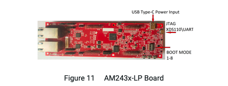
Another USB type C interface on the evaluation board is used for power supply, and the current of the whole board will be about 2A. Here, it is recommended to connect micro USB first, establish serial port connection, and then connect USB type C interface. The connection line of USB type C needs to use a standard full-function connection line, otherwise it cannot communicate normally with the CC logic controller tusb320lairwbr on the evaluation board, resulting in abnormal output current configuration and failure to correctly supply power to the evaluation board.
Figure 11 AM243x-LP Board
After two USB cables are normally connected, four LED lights will be lit on the board, namely ld6, LD7, LD8 and LD11. The ld9 red light will light once at the moment of USB type C insertion, and then turn off. If it is always on, it indicates that there is a problem with the power supply.
Figure 12 AM243x-LP Board LED Status
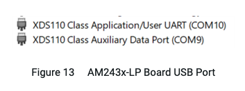
After the micro USB cable is connected, the windows system will install the xds110 driver (CCS will bring its own driver during installation). After installation, two corresponding devices will appear in the device manager, as shown in the following figure.
Figure 13 AM243x-LP Board USB Port
User UART corresponds to the USB to serial port available for users to print logs. In the am243x LP evaluation board, it corresponds to the main of am243x_ UART0 interface.
The following figure shows the four keys on the am243x LP evaluation board. Their functions are as follows:
Figure 14 AM243x-LP Board Push Buttons
Before understanding these different resets, let's first look at the two domains composed of the entire chip of am243x, MCU domain and main domain, which are composed of the following sub modules.
Figure 15 AM243x Power Domain
We can see that different domains contain different modules and peripherals, which determines the control of different domains over different peripherals and modules. In the reset part, different domains can be controlled independently through different reset sources, or the scope of their control domains can be changed through configuration.
MCU_ Porz: it can be regarded as the cold start reset of the whole chip (MCU + main), and the dynamic boot mode can be changed without power failure;
MCU_ Resetz: Hot reset of MCU domain;
SoC_ RESET_ Reqz: Hot reset of main domain;
On the am243x LP evaluation board, the boot configuration can be changed by the 8-bit dial switch. The 8th bit is not used and is in the suspended state. The following table lists the boot mode corresponding to the 7-bit configuration.
Figure 16 AM243x LP Boot Mode Selection Table
The three commonly used modes are shown in the figure below:
Figure 17-1 AM243x LP Boot Mode Switch
For the backup boot mode, the am243x LP is configured as none mode by default (bootmode13:10 = x 0 0 0), which is not concerned here for the time being.
Figure 17-2 AM243x LP Boot Mode Switch (Backup Mode Configuration)
You can change the configuration of the dial switch when the power is off, and then power on again. Or change the dial switch when powered on, and then use the SW1 button to realize MCU_ Porz cold reset to make the new boot mode effective.
4. Introduction to SBL in SDK routine:
If you want to compile the SBL program in the SDK in CCS, you need to install OpenSSL. You can download the light version at the following address,
https://slproweb.com/download/Win64OpenSSL_Light-3_0_0.exe
During installation, pay attention to selecting the windows system directory option.
Figure 18 OpenSSL Installation
After installation, you need to add the following path to the path variable of windows system.
C:Program FilesOpenSSL-Win64bin
When finished, you can import C: timcu_ plus_ sdk_ am243x_ 0x_ xx_ xx_ Xxexamplesdriversboot routines, and compile. Here we import SBL_ OSPI projects in this folder.
Figure 19 SBL Boot Project
SBL null: This SBL only initializes MCU and sets the kernel to WFI mode (wait for interrupt);
SBL OSPI: initialize MCU, read and start multi-core appimage code from 0x80000 address of OSPI flash;
SBL OSPI multi partition: initialize MCU and read the code of each kernel from different offset addresses of OSPI flash;
SBL UART: initialize MCU, read and start multi-core appimage code from UART through XMODEM protocol;
SBL UART uniflash: a flash writer program combined with py script, which is used to burn OSPI flash;
4.1 SBL boot image creation
SBL is similar to general applications. It can be created and compiled through CCS The details of the conversion process from out file to boot image are as follows:
Although the SBL project is similar to the application, the entry address of the SBL is different from that of the user application. The ROM code of am243x will configure the entry address of the program to both r5fss0-0 and r5fss0-1 cores at the same time. Considering that SBL only runs on r5ss0-0, we need to put r5fss0-1 in WFI mode and only run r5fss0-0 kernel. This operation can be done by adding the link parameter - E_ vectors_ SBL.
Figure 20 AM243x Link Command
After entering the main () function, you must first call bootloader_ Socloadsysfw to load sysfw into the cortex m3 kernel of dmsc for board config operation.
Note: sysfw defaults to H header file is compiled and linked to SBL. During startup, it will be sent to the dedicated RAM area of dmsc kernel. The contents of sysfw file are in C: timcu_ plus_ sdk_ am243x_ 0x_ xx_ xx_ xxsourcedriverssciclientsocam64x_ am243x sysfw_ signed. H inside.
Figure 21 Bootloader_ socLoadSysFw
In SBL, vectors are linked to 0x7000000 by default, and the address space of ATCM (a tight coupled memory) and btcm (b tight coupled memory) cannot be used in SBL. SBL can only use the space in the address range of 0x70000000 to 0x70080000, including code, data and stack.
After compilation, SBL The out file will be converted into a through objcopy in GCC Bin file, and then the bootable will be generated by signing scripts Tiimage file, a default key will be used to sign here. This process needs to be followed even for unsafe startup MCU chip. This signing script will use OpenSSL installed earlier.
When loading SBL, RBL needs to be in the signed format. You can sign the SBL through the following command.
cd C:timcu_ plus_ sdk_ am243x_ 0x_ xx_ xx_ xxtoolsbootsigning
.x509CertificateGen. ps1 -b {BOOTIMAGE_BIN_NAME} -o {BOOTIMAGE_NAME} -c R5 -l 0x70000000 -k rom_ degenerateKey. pem -d DEBUG -j DBG_ FULL_ ENABLE -m SPLIT_ MODE
Here, we use the bin file generated by a routine to demonstrate. First, copy the bin file generated by CCS to C: timcu_ plus_ sdk_ am243x_ 0x_ xx_ xx_ Xxtools bootsigning, which is convenient for operation on the command line.
Figure 22 Signing Files Folder
Note: the PowerShell command line environment under Windows 10 is used here. Enter PowerShell and execute it in the start menu to enter the interface. The company's computer may limit the execution permission of PowerShell, which will be prompted during execution.
.x509CertificateGen. ps1 -b sbl_ ospi_ am243x-lp_ r5fss0-0_ nortos_ ti-arm-clang. bin -o sbl_ ospi_ am243x-lp. tiimage -c R5 -l 0x70000000 -k rom_ degenerateKey. pem -d DEBUG -j DBG_ FULL_ ENABLE -m SPLIT_ MODE
At this point, we can see the final generated tiimage file that can be used to start the SBL.
Figure 23 Powershell console command execution
Figure 24 Signing result of tiimage
5. SBL burns and guides the application to run:
Let's quickly verify that SBL is booted and running with the user application.
5.1 installing Python script
Onboard external QSPI flash needs to be burned through Python script, and the required Python 3 environment download address is as follows.
https://www.python.org/downloads/windows/
Note that when installing python, you need to add the python path to the system path. After installation, you can verify whether the installation is successful under the CMD console.
Figure 25 Python Installation
Figure 26 Python Environment Check
Next, you need to execute the following command to install the components related to serial port download. Note that you need to open the CMD window in administrator mode.
pip install --upgrade pip
pip install pyserial xmodem tqdm
Figure 27 Python toolset installation
5.2 generating application code
After opening CCS, import the ADC driver routine of SDK. The path is as follows.
C:timcu_ plus_ sdk_ am243x_ 0x_ xx_ xx_ xxexamplesdriversadcadc_ singleshotam243x-lpr5fss0-0_ freertos
Figure 28 Import SDK ADC example into CCS
Figure 29 Confirm the example import
Figure 30 Build the example
After compiling the project, we can see the generated relevant files, including Appimage is the file that the application will burn to the external SPI flash.
5.3 burning OSPI SBL files and application codes using UART startup mode
The next burning operation needs to be operated in the command console of windows. In order to facilitate this process, we can directly execute it by using bat files to improve efficiency.
ADC in the workspace directory of CCS_ singleshot_ am243x-lp_ r5fss0-0_ freertos