Quiescent current (IQ) is usually defined as the current consumed by an integrated circuit (IC) under no-load and non switching but enabled conditions. Broadly speaking, quiescent current is the input current consumed by IC in any ultra-low power state. This definition is more helpful for us to understand the connotation of quiescent current.
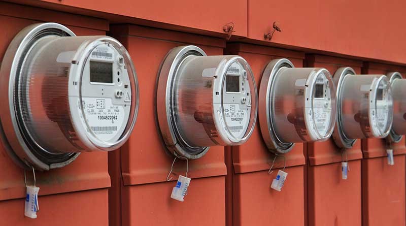
For battery powered applications, this input current is provided by the battery, which determines how long the battery needs to be recharged (rechargeable battery such as lithium ion or nickel hydrogen battery) or replaced (primary battery such as alkaline battery or lithium manganese dioxide). For battery powered applications in standby or sleep mode for a long time, the battery running time may vary by several years due to the influence of quiescent current. For example, an ultra-low quiescent current boost converter such as tps62840 of 60NA is used to power normally open applications (such as the smart meter in Figure 1), and its battery operation time can reach 10 years.

Figure 1: smart meter
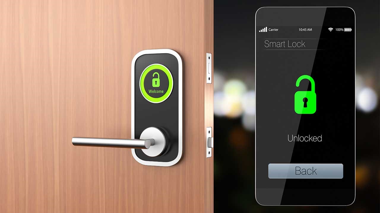
Quiescent current will also affect the running time of batteries in our daily equipment. For example, after you buy a smart watch, you will charge it for an hour before using it. Or, you always carry the physical key at home to prevent the battery of the smart lock (as shown in Figure 2) from running out. The above two scenarios are also inseparable from quiescent current.

Figure 2: smart lock application
In this article, I will introduce three common specifications related to quiescent current in the DC / DC converter data sheet - off current, non switching quiescent current and switching quiescent current, and explain how these specifications affect the system power consumption.
Addressing the low quiescent current challenge in low power applications
Turn off current
The off current is measured when the IC is off or disabled. Therefore, you may think that the non switching quiescent current should always be zero. In fact, some ICs will have leakage current in this state, while other ICs actually have internal circuits. Even when the IC is disabled, the internal circuits will consume a small amount of current to maintain the housekeeping function.
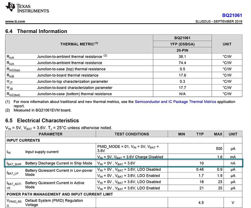
Take consumer electronics products placed on store shelves as an example. The reason why your smart watch cannot work immediately after purchase is related to the off current specification of its IC, as shown in Figure 3. When terminal products are placed on store shelves or stored in warehouses for a long time (the temperature may rise, resulting in faster battery depletion), the devices (such as most DC / DC converters) are turned off. Therefore, although the DC / DC converter is disabled, the battery is still discharging slowly.

Figure 3: battery discharge current of bq21061 in transport power saving mode
Some ICs have a variety of off states, such as 2Na transport mode of TI's bq25120 battery charger or 4na bypass mode of tps61094 boost converter. In these advanced off states, very limited device functions are usually enabled in order to consume only a very small amount of quiescent current. Compared with bq25120 high impedance (off) mode with static current of 700na and tps61094 off mode with static current of 200na, transport power saving mode and bypass mode can prolong the battery operation time by 350 times and 50 times respectively.
Non switching quiescent current
The non switching quiescent current is the current when the IC is enabled, between switching pulses and no load. This parameter can be easily measured by mass production automatic test equipment, so it can be found in the data sheets of most switched DC / DC converters.
Although different ICs can be compared according to the non switching quiescent current, this method can not estimate the battery running time most accurately for two reasons: the non switching quiescent current is different from the consumed battery current, and many ICs consume quiescent current through input voltage and output voltage at the same time. However, since the output voltage and its quiescent current are fundamentally from the battery at the input end, additional conversion or measurement is required to obtain the equivalent quiescent current of the input power supply - the total consumed battery current cannot be obtained by simply adding the two quiescent current values. For example, the tps61099 boost converter can consume 400na quiescent current from the input voltage and 600na quiescent current from the output voltage, but its no-load input current consumption is about 1.3 µ a instead of 1 µ a.
Switching quiescent current
Switching quiescent current has many different names: working quiescent current, standby current, sleep mode current, no-load input current, grounding current of low voltage drop linear regulator (LDO), etc. It is the input current actually measured when the IC is working and does not provide any load current. Since the switching quiescent current is measured in the actual situation rather than on the mass production line, the IC occasionally switches to reduce the loss and supplement the leakage at the output.
This parameter is the most accurate estimation of the battery current consumed under no-load state, which can be found in many data tables. For example, the switching static current of tps62840 is 60NA, as shown in Figure 4.

Figure 4: 60NA quiescent current DC / DC converter
For applications that maintain ultra-low power consumption most of the time, the use of low quiescent current DC / DC converter is very important to realize the battery running time required by the application. For example, the smart lock is in a state of ultra-low power consumption most of the time, waiting for the mobile phone to send the unlock code. If the switch quiescent current is too high, most of the battery power will be consumed in waiting rather than for switch lock.
epilogue
This paper briefly introduces the common specifications of quiescent current in data sheet and its influence on battery running time. To learn more about quiescent current, please refer to the white paper "overcoming low IQ challenges in low-power applications", read the author's article "quiescent current: definitions, common misunderstandings and how to use it" published in the Journal of analog design, or watch a series of low quiescent current training videos to learn more about the topic.