Compared with battery chemicals such as lithium manganese dioxide (LiMnO2), lithium thionyl chloride (lisoci2) battery can achieve higher energy density and better cost per watt, so it is widely used in intelligent flowmeter. However, one disadvantage of lisocl2 battery is its poor response to peak load, which may reduce the available capacity of the battery. Therefore, in this paper, we will explore an effective method to reduce the battery peak load (hundreds of milliamps), so as to help prolong the battery life.
It is very important to improve the available capacity of the battery to a greater extent, because this can enable the system design to achieve:
Increase the number of meter readings and data transmission under the condition of using the same battery.
Longer life under the condition of using the same battery.
Reduce the battery size without changing the working life.
By applying the same design to more types of flow meters, the above advantages can reduce battery cost, maintenance cost and development cost to a greater extent.
Watch tps61094 demo video
Design challenge: extending battery life
Successful instrument design requires long-term operation time (more than 15 years) and functions such as valve control, data recording and data transmission. Prolonging battery life is an effective way to prolong instrument operation time. However, if the battery is directly connected to the load without any power buffer, the complex load curve of the instrument may shorten the battery life.
According to different current levels, the load consumption curve of standard instruments can be divided into standby mode, intermediate mode and working mode. Each mode has different effects on battery life:
The current consumption in standby mode is 5 µ a to 100 µ a. The main power consumption items are quiescent current (IQ) of metering, microcontroller and protection circuit. Although its absolute value is very small, it is usually the main factor affecting the service life of the instrument. When in standby mode, the IQ of any connected DC / DC converter shall be at Na level, and the leakage value of power buffer shall be at a low level, so as to improve efficiency.
The current consumption of intermediate mode is 2mA to 10mA. Usually, this kind of load comes from the analog front end of Rx phase. In this mode, the efficiency of the power buffer is very important to reduce energy loss to a greater extent.
The current consumption is the highest in operating mode. In the operating mode, the load usually comes from the drive valve and analog front end in TX stage, which requires a current of 20mA to hundreds of Ma. Obtaining current directly from the lisocl2 battery will seriously reduce the battery capacity.
Table 1 shows the capacity derating of saft LS33600 battery based on 17ah rated capacity under different load and temperature conditions. When the operating temperature is + 20 ° C, 200mA load current will reduce the capacity by 42%. Therefore, never directly use the battery to supply power to the load. The peak current can be limited below 10mA only by using a low leakage power buffer.

Table 1: capacity and current characteristics of saft batteries LS33600 battery
Ti tps61094 60NA IQ buck / boost converter can prolong battery life while maintaining excellent efficiency in standby mode, intermediate mode and working mode. Tps61094 has three main benefits:
Ultra high efficiency over a wide load range. When Vout = 3.3V and Vin is greater than 5V and the load is 5 µ a to 250mA, tps61094 can achieve an average efficiency of more than 90% and achieve efficient power supply in most flowmeter use cases.
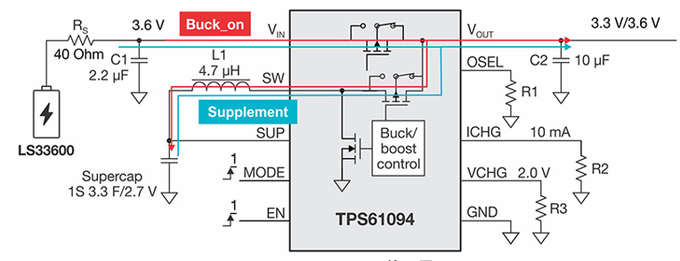
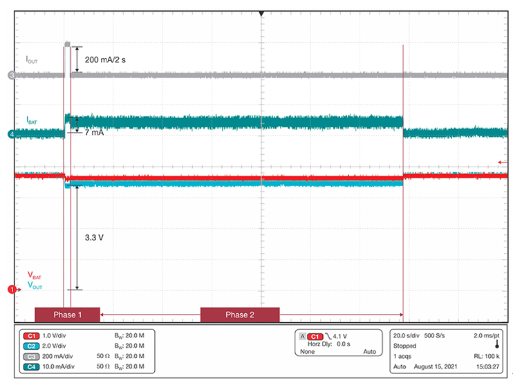
Limit the peak current of the battery. In Buck_ When charging the supercapacitor in on mode or using the battery to supply power to the heavy load at Vout terminal in supplementary mode, tps61094 can limit its peak input current. Figure 1 shows the configuration of tps61094, and Figure 2 shows the battery peak current when there are 200mA and 2S load pulses at Vout end. Under the heavy load condition of stage 1, the peak current is limited to 7ma. After the second stage load is released, the device charges the supercapacitor with a constant current of 10mA. When the voltage of the supercapacitor is restored to 0V after charging, the device will stop charging, but it is still in buck_ On mode.

Figure 1: configuration of tps61094

Figure 2: oscilloscope displays the result of battery peak current under heavy load
The energy provided by the supercapacitor remains unchanged over the whole temperature range. Generally, using hybrid layer capacitor (HLC) or electric double layer capacitor (EDLC) as power buffer can improve pulse load capacity. However, the energy stored in these passive devices depends on the battery voltage. When the temperature decreases, the battery voltage will also decrease, which will weaken the pulse load capacity of HLC or EDLC and increase the power supply current of the battery. To solve this problem, tps61094 will keep the voltage of the supercapacitor stable and will not change the voltage no matter how the temperature changes.
The available energy in the supercapacitor depends on the capacity of the supercapacitor, the set maximum voltage at both ends of the supercapacitor and the undervoltage locking function of tps61094. The more energy available, the longer the working time under continuous heavy load.
Figure 3 shows a power buffer solution using tps61094 or using only supercapacitors, respectively. In the tps61094 solution, the supercapacitor voltage is set to 2V. When tps61094 supplies power for continuous load, it can absorb power from the supercapacitor until the supercapacitor voltage drops to 0.6V. Therefore, the available energy on the supercapacitor can be calculated with the help of Formula 1:
(1)
Among them ŋ Is the average efficiency of the converter.
Under the worst-case temperature of – 40 ° C, the tps61094 can achieve an average efficiency of 92% when the input voltage is 2V to 0.6V and the current is 150mA. Formula 2 shows the calculation result as follows:
(2)

Figure 3: tps61094 and HLC / EDLC configuration
In HLC or EDLC solutions, the available energy varies with the battery voltage. When the temperature is – 40 ° C and the current is 10mA, the LS33600 voltage will drop to 3V. Use formula 3 to calculate the available energy as:
(3)

Comparing the results of formulas 2 and 3, it can be found that the available energy of tps61094 solution is twice that of HLC and EDLC solution. This means that more energy is delivered to the load, and in extreme cases, the peak current of the battery will be reduced. For example, if a 200mA load is used to drive the valve at a voltage of 3.3V, the HLC or EDLC solution can only support the load for 2.8s. The tps61094 buck / boost converter with integrated supercapacitor can support loads for up to 7.8s (assuming that all loads are powered by the power buffer).
epilogue
The flowmeter has a complex load consumption curve, so a power buffer is required to help prolong the life of lisocl2 battery. Tps61094 can achieve excellent efficiency in a wide working range and is an ideal choice to solve the problem of life length. By limiting the peak current of the battery, this step-down / step-up converter can greatly improve the capacity and the available energy of the supercapacitor, and make the system work longer at low temperature than HLC or EDLC solutions.